View Frustum culling
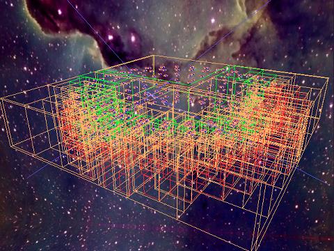
This demo supports view frustum culling. Each object must define a bounding sphere and a bounding box that totally encloses the object. Before drawing, it is then checked whether these simple geometrical objects lie fully inside or fully outside of the view frustum of the camera or if they are partially visible. Objects that lie completely outside of the view frustum do not have to be drawn. To make such a test even more efficient, it is possible to group a set of objects together and define a bounding volume for the whole group. The image on the left shows the camera with its view frustum (which is defined by six planes) and some object that are tested with their bounding boxes. Green boxes mean that the whole box lies inside the frustum, red boxes signal the the object lies fully outside and a brownish box means that we cannot say for sure yet. The implementation features bounding spheres and axis aligned bounding boxes for the view frustum culling test. It is interesting to note that, because of the nature of the underlying framework (having scene-graph like hierarchies of local coordinate systems), these bounding boxes are just locally axis aligned, from a global point of view, they may not be aligned (this is also shown in the picture to the left). The framework also allows for an automated computation of the bounding volumes for grouped objects. If the objects of such a group do not rotate, such a computation may evan yield an optimal solution. Furthermore, the framework can also handle moving objects by calculating a static (non changing) bounding volume that will always contain the object at every point in time. All the volumes are precomputed and the structure of the grouping is never altered.
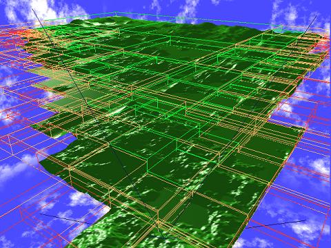
Level Of Detail
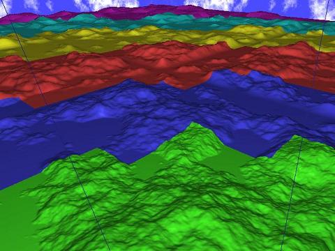
The image to the left shows the second scene of the demo, which contains a landscape with hills. Level of detail, as it has been implemented with this demo, allows to draw different objects depending on the distance of such an object to the camera. This is illustrated in the picture by having different colored objects for each level. It is apparent that the hills that are close to the camera have a much higher complexity than the hills that are far away from the camera, which consist only of a few polygon faces. The demo currently features only static level of detail, which means that different levels of detail of an object and the distances at which they get drawn is fixed and there is no geometry data generation nor changing of distance thresholds on the fly.
Perlin Noise
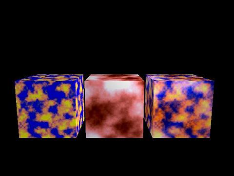
The demo also features a class than can generate 2D Perlin Noise. Perlin Noise can be described as a weighted summation of noise at differnt frequencies. The image shows two such generated noise patterns on the left cube and on the cube in the middle of the image. The cube on the right shows a combination of the other two perlin noise textures, which can also be generated with the perlin noise class of the demo.
Perlin Noise is used for differnt things in this demo. The texture of the torus in the first scene is exactly the texture of the right cube. The sky in the second scene is also just perlin noise and the height field used to generate the landscape is ... (you may have guessed it already) ... Perlin Noise.
Scene 1
The first scene of the demo is a big torus that is composed of many small tori. This big torus is constructed recursively. During the recursion, objects that are close together get grouped together. The final result is a group hierarchy of logarithmic depth (which makes the view frustum culling quite effective).
The camera is moved using keyframe interpolation. As every other object in the demo, the position of the camera is defined by an coordinate offset from the origin (translation) and three euler angles which get applied according to the RPY-convention (roll around x-axis, pitch around y-axis, yaw around z-axis). Interpolating between various checkpoints over time in different ways (linearly, using sine or cosine, using differnt methods for the differnt variables, ...) defines the camera path.
Scene 2
The second scene is a flight over a landscape, which is generated from a height field. In order to get a better resolution for the level of detail, the landscape is subdivided into small patches, which are (like in the first scene) grouped together and build an hierarchy. The resulting landscape is additionally repeated and the repetition is made less apparent by further grouping and a randomly rotating these groups. The differnt levels of detail for the landscape are created by ignoring certain points of the height field. This whole computation is done at the start of the demo, no geometrical models get computed on the fly.